 ar
ar bg
bg hr
hr cs
cs da
da nl
nl fi
fi fr
fr de
de el
el hi
hi it
it ko
ko no
no pl
pl pt
pt ro
ro ru
ru es
es sv
sv tl
tl iw
iw id
id lv
lv lt
lt sr
sr sk
sk sl
sl uk
uk vi
vi et
et hu
hu th
th tr
tr fa
fa ms
ms hy
hy ka
ka ur
ur bn
bn mn
mn ta
ta kk
kk uz
uz ku
ku
load cell wire diagram
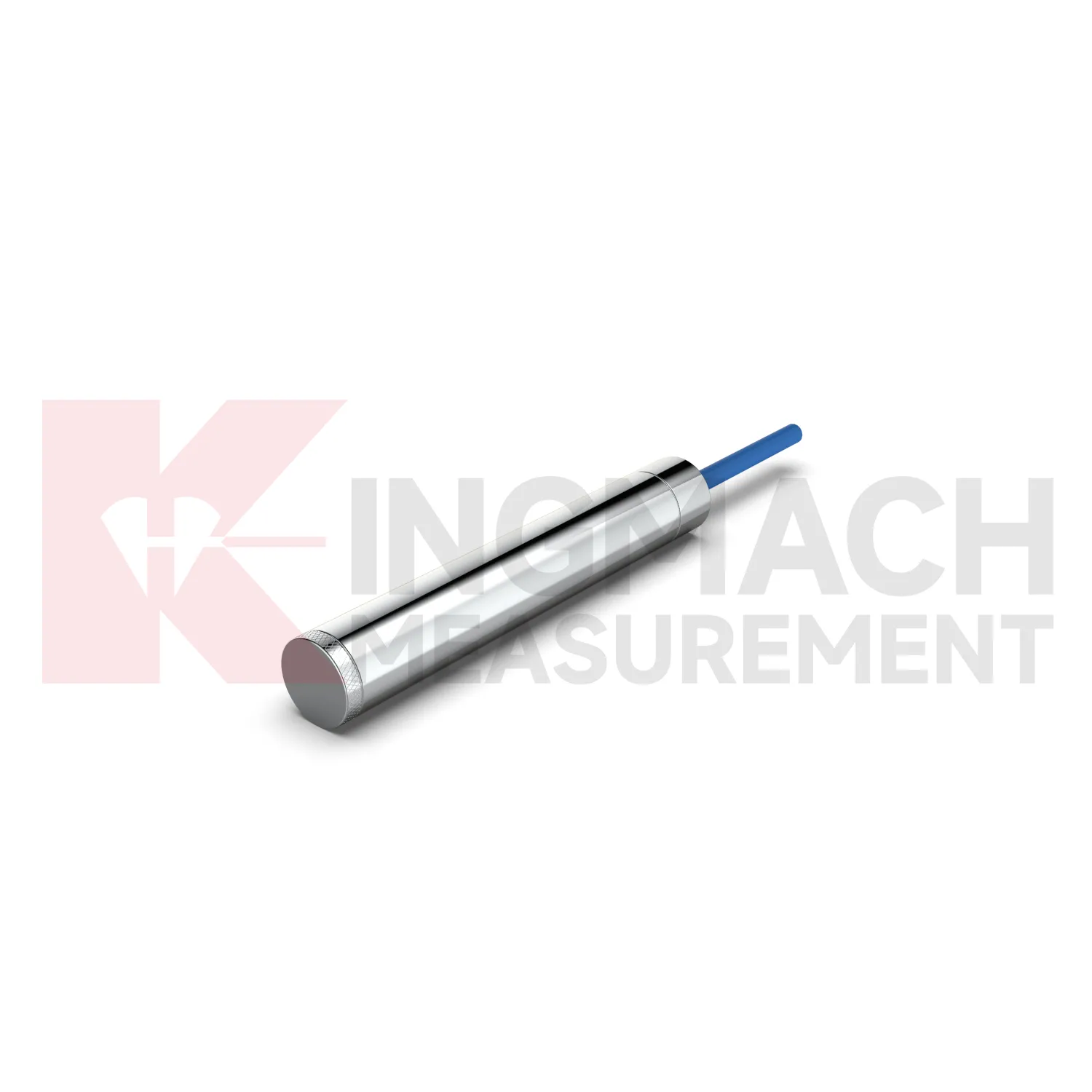
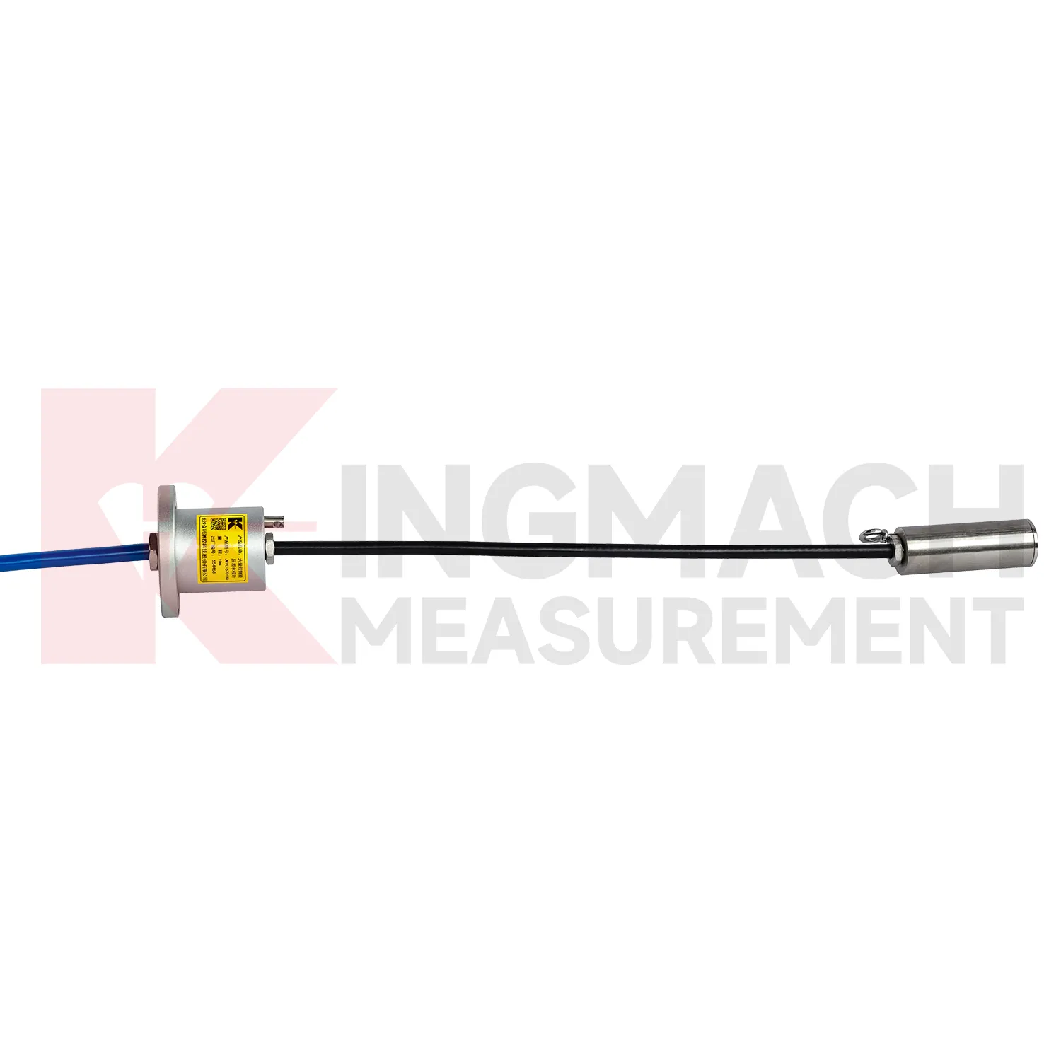
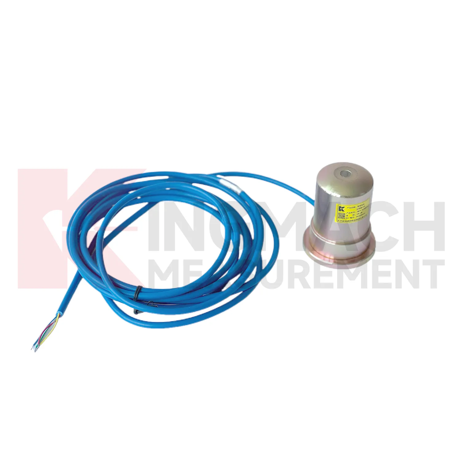
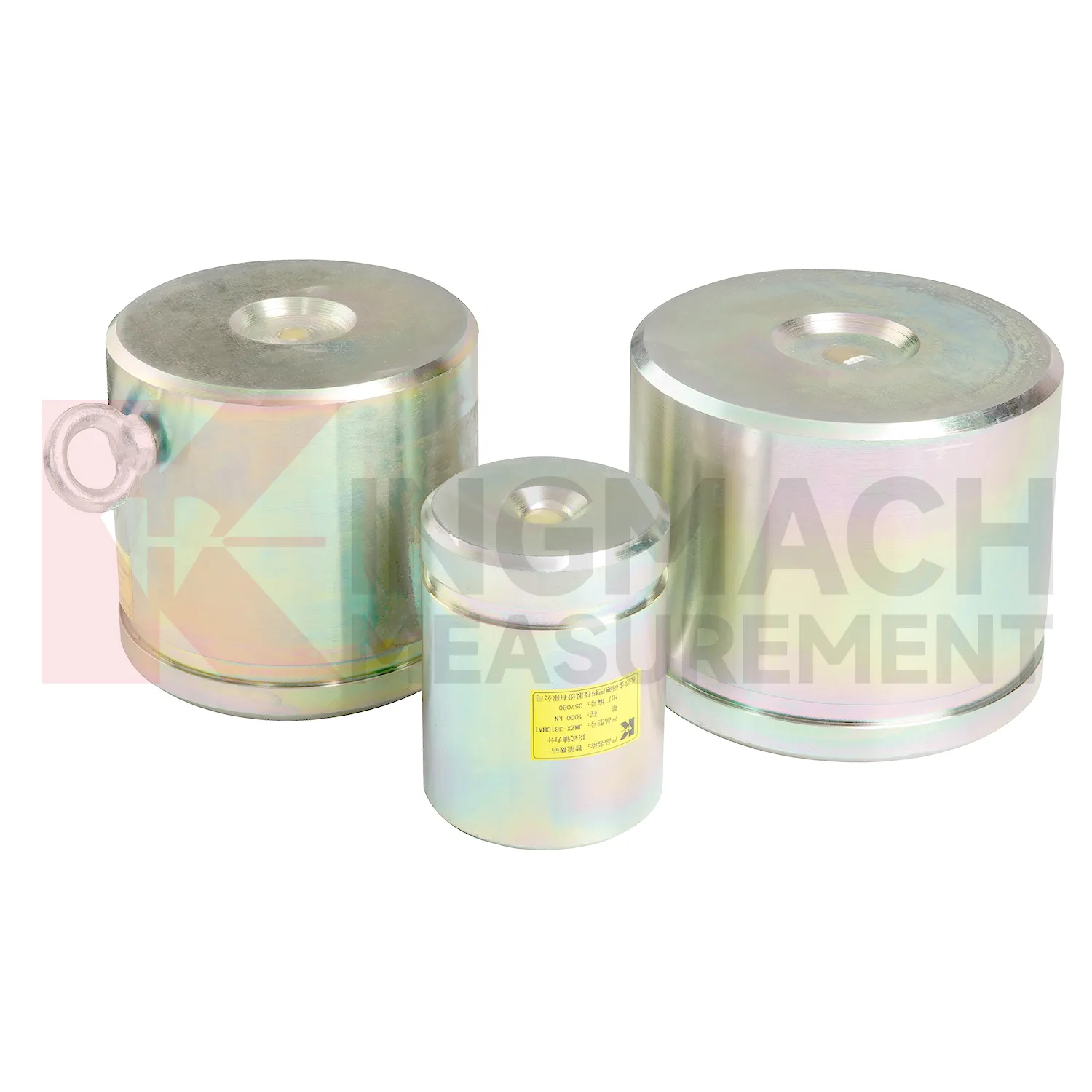
Kingmach load cell wire diagram products are built for projects that need force data with a clear technical trail. The hollow load cell JMZX-3XXXHAT uses an annular multi-string elastic steel structure and is listed from 500 kN to 8000 kN, with 0.1 kN sensitivity on the 500 kN model and 1 kN sensitivity on larger models. Its product file also lists a 50 year design life, digital output, automatic temperature correction, waterproof durability, and storage for 800 measurement records. Those details are relevant in bridge cable force monitoring, anchor testing, and long term structural health monitoring, where the same point may be checked for many years. Kingmach, based in Changsha, supplies sensors with readouts, data loggers, DTUs, and software platforms, so the measuring point can be connected to a wider monitoring network. For a project team, the important value is not a catalog claim. It is the ability to identify the sensor, read the same force channel consistently, compensate temperature influence, and keep a documented record when access becomes difficult after construction. For brand context, Kingmach Measurement & Monitoring Technology Co., Ltd. works from Changsha, Hunan, and its product pages group load sensing with structural health monitoring, engineering monitoring sensors, readouts, data loggers, instrumentation cables, and visualization software. That catalog context matters because a force sensor is often purchased with the equipment needed to read and archive it.
Application of load cell wire diagram
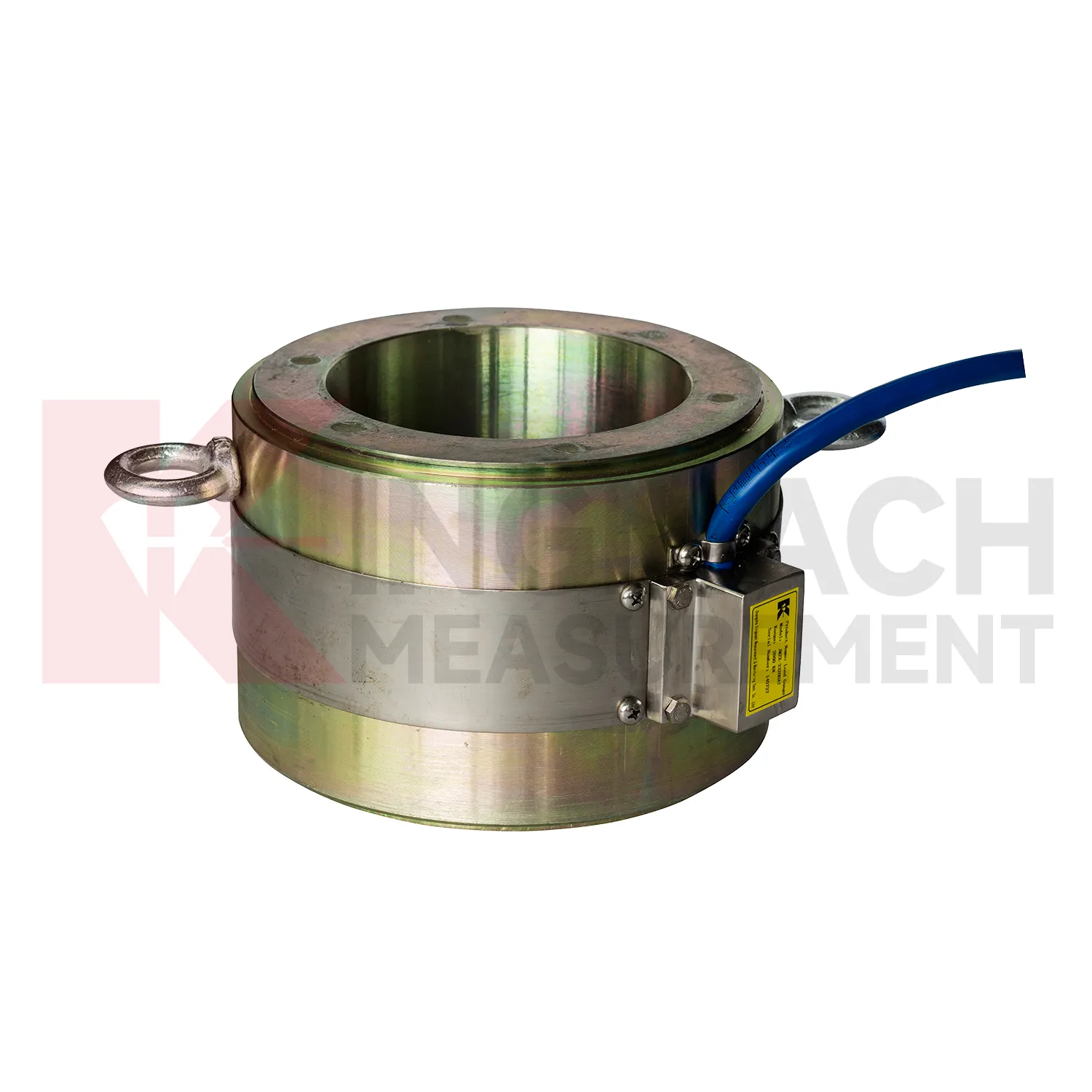
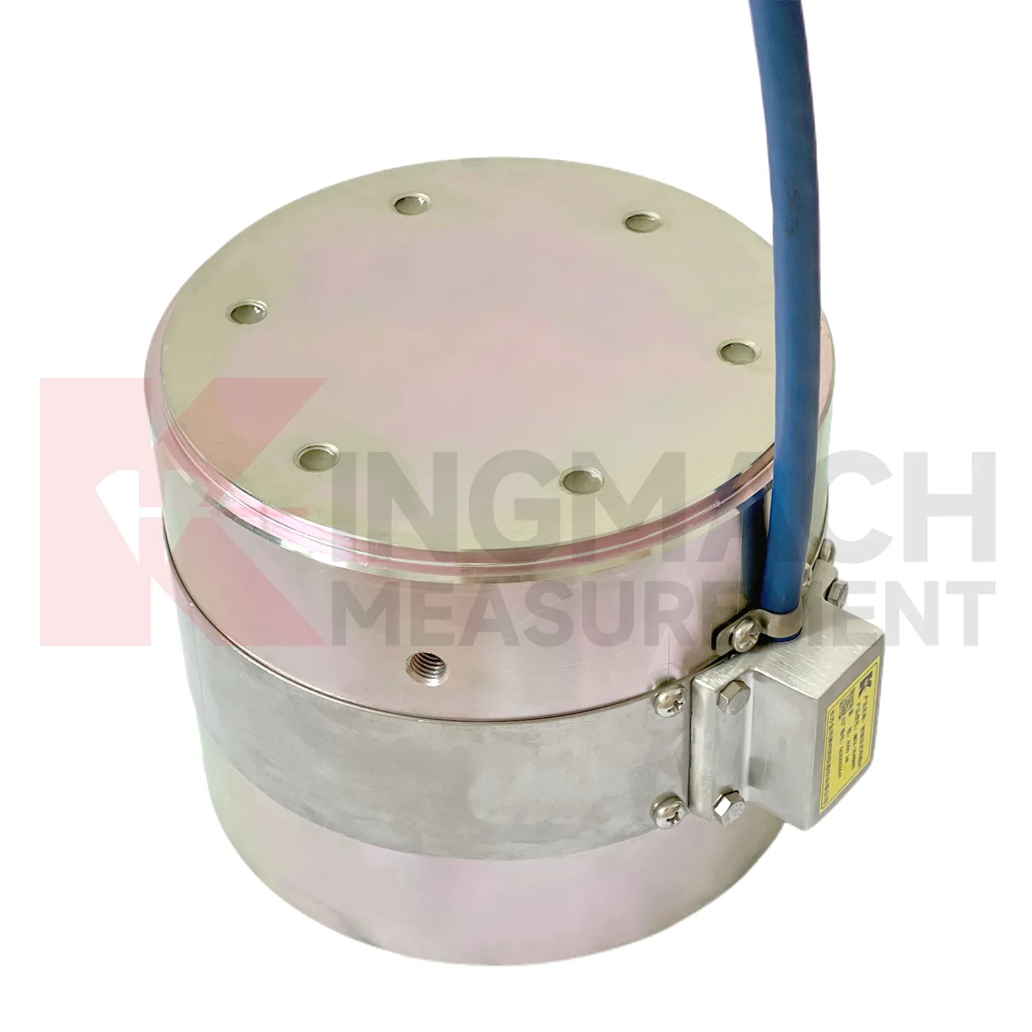
In building structural health monitoring, load cell wire diagram can be used around transfer structures, temporary supports, column load checks, foundation testing, and heavy equipment installation areas. The monitoring need is often construction stage control rather than a permanent visible defect. Loads may shift when floors are cast, jacks are released, shoring is removed, or new equipment is placed. Kingmach solid load cells offer 1000 kN to 10000 kN ranges, 0.1 kN resolution, and 0.5%FS precision, with a -30°C to 80°C working temperature range. Axial force meters add direct kN display for steel support points and 0.5%FS accuracy. These parameters help site teams check whether the support path is behaving as planned. The reading should be reviewed together with settlement, tilt, crack gauges, and construction sequence notes. For long term building owners, retaining the original model, calibration coefficient, zero value, and first stable reading makes later inspection far easier when occupancy, equipment load, or renovation changes the load pattern. In buildings, temporary works often disappear after the next construction stage, so the early record should be complete. Photographs of the installed point, bearing plates, cable path, and readout channel can prevent confusion during later structural review.
The future of load cell wire diagram
Industrial and test bench use of load cell wire diagram will likely move toward automated verification. High capacity solid load cells with 0.5%FS precision and ranges up to 10000 kN can already support heavy compression tests, jack calibration work, and equipment checks. Future systems can connect these instruments to local software that records test stages, operator notes, temperature, overload events, and calibration status. That reduces the risk of a handwritten record being separated from the force data. Edge acquisition can also prevent common errors by warning when the zero point is unstable, the load rate is outside procedure, or the sensor range is being approached too quickly. Kingmach's smart memory features fit this direction because the sensor can carry identity and calibration background. The strongest future workflow will combine rugged hardware, automatic records, and simple review tools, so a test can be repeated months later with the same measurement basis. The same logic applies to factory tests and site acceptance.
Care & Maintenance of load cell wire diagram
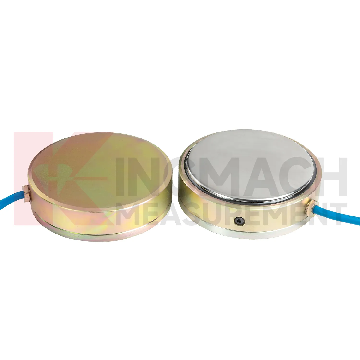
For load cell wire diagram installed in foundation pits or tunnels, the maintenance routine must fit a fast changing site. Axial force meters may cover 200 kN to 3000 kN with 0.5%FS accuracy and direct kN display, while earth pressure cells may cover 0.3 MPa to 8 MPa with 0.001 MPa resolution. During installation, confirm that steel support surfaces have enough thickness and strength, and add buffer plates where stress concentration is possible. Protect the sensor body and cable from equipment impact, cutting, concrete splash, and standing water. During excavation, check readings after each major stage rather than waiting for a fixed calendar date. If a channel becomes unstable, inspect the cable route, connector, readout, and temperature condition first. Long term points should have waterproof labels, photo records, and clear channel mapping. Sudden changes should be compared with wall movement, settlement, water pressure, and site work before any conclusion is recorded.
Kingmach load cell wire diagram
load cell wire diagram can be treated as a field witness for hidden force transfer in civil structures. Concrete, steel, soil, cable systems, and hydraulic loading may all look calm while the internal load path changes. Kingmach products in this category cover hollow load cells for anchors and cables, solid load cells for compression and pile testing, axial force meters for steel support loads, and earth pressure cells for contact pressure. Each type answers a different site question. Has the anchor lost tension? Is a pile test load centered? Is an excavation support taking more force after the next soil layer is removed? Is water pressure pushing the retaining structure harder after rain? The strongest monitoring records combine the sensor model, calibrated coefficient, zero value, temperature, reading time, and construction stage. That record gives owners a way to compare today with last week, last season, or the previous loading step, instead of relying on a single inspection note.
FAQ
Q: Can load cell wire diagram be used for soil pressure or retaining wall pressure? A: Yes, pressure related models such as earth pressure cells are used where the measured value is contact pressure rather than direct member force. Q: What ranges are listed for Kingmach earth pressure cells? A: The JMZX-50XXAT/ATM family lists 0.3 MPa, 0.6 MPa, 1 MPa, 2 MPa, 4 MPa, 6 MPa, and 8 MPa ranges. Q: What accuracy and resolution are listed? A: The product file gives 0.001 MPa pressure resolution, 0.5%FS pressure accuracy, and ±0.5°C temperature accuracy. Q: Where are these readings useful? A: Foundation pits, dams, slopes, retaining walls, embankments, tunnels, and buried structures. Q: What maintenance issue is most common? A: Cable damage, water entry, channel confusion, and poor installation records cause many field doubts.
Reviews
Michael Anderson
The strain gauges and load cells are extremely accurate and stable. They performed very well in our bridge monitoring project. Highly recommended!
Ryan Lewis
Fast delivery and excellent product quality. The accelerometers and tiltmeters are highly reliable. Strongly recommend this company.
Latest Inquiries
To protect the privacy of our buyers, only public service email domains like Gmail, Yahoo, and MSN will be displayed. Additionally, only a limited portion of the inquiry content will be shown.
Olivia***@gmail.comUnited States
Hello, we are currently sourcing high-precision strain gauges and load cells for a bridge monitoring...
Charlotte***@gmail.comUnited Arab Emirates
Hi, we require instrumentation cables suitable for harsh environments. Could you advise on specifica...